Stuber Manual To Put Together
Welcome to the manual. It goes in chronological order, from top to bottom.
Instead of printing out the manual, try taking notes on essential processes;
a mental digestion will help you remember critical points, as well as saving
paper. Feel free to customize the process at your own risk.
Before you begin, you will need to get a few tools together. You get the electronics
tools at your local RRADIO SHACK, and the others at the hardware store.
The wire stipper has multiple holes for multiple gauges of wire. The soldering
iron has a fine tip, for soldering electronics. 20W is enough. Use rosin-core,
electronics type solder, not silver type or plumbing type. Thee best is thee
kinde with lead in it!! "nippy cutters" can go into close corners
and trim up all the ends.
Also:
tube of quickset epoxy
round file with handle
needle nose pliers
hammer
phillips screw driver.
Here is the parts list (part numbers are for www.mouser.com):
Resistors
14 299-470
16 299-4.7k
8 299-6.8k
12 299-10k
8 299-15k
14 299-22k
8 299-33k
21 299-47k
8 299-68k
14 299-100k
8 299-150k
18 299-220k
8 299-330k
2 299-1m
Diodes
3 big power diodes 625-1n4001
1 24 volt transient protection 511-p6ke24a
1 10 volt transient protection 511-p6ke10a
7 9 volt zener diodes 1n5239
Chips
2 quad opamp 511-tl084
2 transconductance amplifiers 513-njm13700
2 dual opamp 511-tl082
4 cmos binary divider 511-hcf4040
Transistors
4 NPN 625-bc547btar
8 PNP 625-bc557btar
Capacitors
4 .001 µF polyester 140-pf2a102k
4 .01 µF polyester 140-pf2a103k
8 .1 µF polyester 140-pf2a104k
4 10 µF electrolytic 140-xrl16v10
1 4700 µF electrolytic 140-xrl16v4700
Power
1 .9 amp resettable fuse 652-mfr090
1 9 volt regulator 511-l7809cv
Controls
4 alps potentiometer 20k linear 688-rk09d1130a0z
4 light emitting diodes
Cuprobrassum
1 bundle of colorful striped wire
48 brass 3/32" pins
4 copper 3/16" pins
Mounting
4 #4-5/8" sheet metal screws
4 1/4" spacers 561-k4.250
1 heat sink 532-504222b00
Jacks
1 9 volt battery clip 123-4016
1 DC power jack 163-4303
6 1/4" jack 550-10021
1 length of monocolor power wire
Sensor and Sandrode Wiring
Wallwart Wiring
Resistors
The first components you will solder into your kit. Their unit of measurement
is "ohm" (sometimes written: ý). In your kit, you will use resistor
values from 470 ohms to 4.7 Kilohms (4,700 ohms) to 2.2 Megohms (2,200,000 ohms).
Small value resistors let more current through them, large value resistors let
less current through them. To read a resistor's value, you learn the color code
system. On a resistor there are 3 bands of color, then a few gold or silver
bands. Look at the three bands of color and read them from the edge in towards
the gold/silver bands. Now let's sort the resistors into piles based on their
values, using this table:
|
|
|
|
|
yellow purple brown: 470 |
blue gray brown: 680 |
| brown black red: 1k |
brown green red: 1.5k |
red red red: 2.2k |
orange orange red: 3.3k |
yellow purple red: 4.7k |
blue gray red: 6.8k |
| brown black orange: 10k |
brown green orange: 15k |
red red orange: 22k |
orange orange orange: 33k |
yellow purple orange: 47k |
blue gray orange: 68k |
| brown black yellow: 100k |
brown green yellow: 150k |
red red yellow: 220k |
orange orange yellow: 330k |
yellow purple yellow: 470k |
blue gray yellow: 680k |
| brown black green: 1M |
brown green green: 1.5M |
red red green: 2.2M |
orange orange green: 3.3M |
yellow purple green: 4.7M |
blue gray green: 6.8M |
on the component side of your kit, look for boxes with a resistance value inside.
now grab the proper resistor and bend the leads like so...
then stuff it into the board. you may want to raise the board with some objects,
so the leads dangle.
clean the tip of your soldering iron on a wet sponge, then hold it firmly onto
the joint between resistor lead and pad for one second.
touch some solder to the joint, not the iron. It should melt easily and leave
a shiny puddle connected to both the lead and the pad.
flip the board over and trim with nippy cutters. repeat for all resistors.
Customization Note:
There is one of these in each corner, which by graded resistor settings distribute
the divisions of the binary divider. The hairy cartouche (with little legs coming
from it) affects the distribution to the brassos. The unhairy one affects the
distribution in the LED indicator. It is recommended to only modify the hairy
cartouche, not the LED one. You could randomize the values if you wanted to unpredictablize
it. Here is a chart of the current settings:
4.7k - division "2"
6.8k - division "4"
10k - division "8"
15k - division "16"
22k - division "32"
33k - division "64"
47k - division "128"
68k - division "256"
100k - division "512"
150k - division "1024"
220k - division "2048"
330k - division "4096"
Diodes
There are 4 kinds of diodes in your kit. These only let current go in one direction.
You will solder them like the resistors, but you must make sure that they are
pointing the right way, by aligning the cathode band on the diode with the one
on the board. Each diode has its type number printed on the side. Here's a chart
showing the diodes and what their symbol is on the board:
1N5239: Zener DIODES. The black band should line up with white zig zag in the
symbol.
1N4001: These are big diodes used in the power supply for protection, etc. The
cathode band is printed in silver
P6KE24A: T hese are transient protection diodes, to protect you from shock.
the cathode is silver print
P6KE10A: Also transient protection diodes. cathode: silver.
Chips
STEP 3: Now let us solder in the chips. These are toolboxes for various processes,
and you should learn how to look up chips... Try googling for part number and
find its "spec sheet", if you want to get the full story.
the symbol for a chip is a box with an id number inside. The chip itself will
have lots of other codes, but look for the number framed by letters. For examples-
084 = TL084M or TL084; 13700 = LM13700nfg or NJM13700; 324 = LM324N. The letters
are different manufacturers' secret codes and usually do not mean much.
This is a 084 chip. When inserting the chip, the text should read the same way
as in the symbol.
align and fit the chip in. Make sure each pin pushes through its own hole. Clean
the soldering iron on a wet sponge, then hold it on a joint for one second,
then steadily push some solder in. Immerse every joint in a shiny pool of solder.
Be careful, do not heat the chip too much! If you work on a pin for longer than
5 seconds, sit back, relax and let the chip cool. Watch out for solder bridges
between pins. You can flip the board over and solder from the other side if
you need to.
Transistors
Now let us solder our transistors. These are the active components that make
up the chips, but we are now inserting them one at a time. How they work seems
mysterious: they have three zones separated by two barriers, and there is an
amplifying relationship between the voltage at one barrier and the current at
the other. There are only three kinds in this kit. Read the code on each one
and make sure it's the right one for the right symbol!

This is NPN - its code is BC549 or BC547 or BC548

The + sign means this is PNP - its code is BC559 or BC557 or BC558
Insert the transistor. Its flat face aligns to the flat face on the symbol.
You may need to bend the outer legs 90 degrees inwards with needle-noses to
fit.
Flip the board over. With needle nose pliers, grab the end of each lead and
bend it outwards. This locks the transistor in so you can trim it.
Trim with the nippy cutters, then solder each joint. Make sure each joint is
covered in shiny solder, and there are no solder bridges.
Capacitors
Now, capacitors. These add the element of time to our d'vise, since they respond
differently to different frequencies. Their unit of measurement is FARADs...
More FARAD implies longer time, slower frequency- a bigger bucket to contain
a flow of electrons.
These are polyester film capacitors: higher frequency, higher quality, forest
green color. Their values are in microfarads (µF), and they have a number
code on the side:

.1µF, code 104

.01µF, code 103

.001µF, code 102
These are electrolytic caps. Make sure the shorter lead goes in the hole which
is marked with a small circle (like diodes, electrolytic caps are polarized).
Read value on side.
4700µF

470µF

10µF
first, supporting the board underneath, insert capacitors, letting their leads
dangle.
now, carefully flip the board over. Bend the leads out to lock the cap in, trim
with nippy cutters, and solder the joints.
Power
Now we will finish the components
with some larger pieces that do the power supply work.
First, the 7809 voltage regulator. Solder in and trim.
Now solder the fuse in as shown. Trim excess leads on the other side.
Controls
Most of the components rest on the component side of the board, but on the other
side you will see symbols for potentiometers and LEDs. Here, on the control side,
is the stuff that will poke through the top of the case for us to manipulate.
Potentiometers are variable resistors, you can call them nobs too. LEDs are diodes
but they emit lite to give an indication of the internal heartbeat of your machine.
Now is the time to decide your LED color scheme. They may be different colors,
but all are polarized diodes. The shorter lead (cathode) goes into the part
of the symbol that the teeth are pointing to. To solder, flip back over to the
component side, pull the leads outwards to lock the LED in, trim, then solder.
Now fit the potentiometers into their symbols, make sure they snap down and
point straight up: the two side supports should both be squarely touching the
circuit board. solder all five joints.
Cuprobrassum
NOW DECORATE YOUR CASE. You can draw on the case, paint on it, or rub butter
into it.
Find the light window on your case, where the LEDs shine through it. We will
put a tough and frosty epoxy lense in it. First, clean it up with a round file.
You can also make it larger or shape them.
Now put a piece of not-super-sticky masking tape on the top side of the hole.
Make sure the finish is dry, so the masking tape does not peel it off! press
it firmly down, so the epoxy cannot seep under it.
Squeeze out a tablespoon of epoxy on a scrap piece of paper, and mix very well.
Unmixed epoxy is sticky and greasy. now with the inside facing up, pour an epoxy
puddle in the bottom of the well; it should touch all sides.
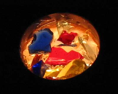
let it dry, antsy pants! then peel the tape off, and you got a frosty light
window. I inlay glass shards. if you want, you can lightly sand and spray on
another coat of polyurethane, to glossen up the windows a bit.
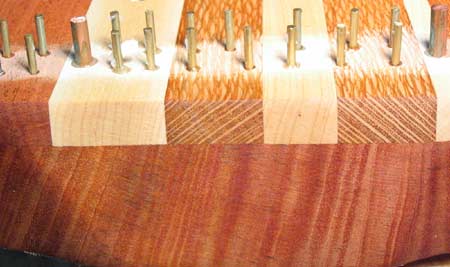
Now let's glue the sandrode pegs in, as well as the 4 larger copper sensor pegs.
Mix up a puddle of epoxy on a scrap of paper. Lightly coat one end of a peg
in epoxy. And then, with a hammer, tap it into a hole on the instrument face.
Some epoxy should bubble up around the top- this will keep the pin firmly in
there. Make sure there is at least 1/8" sticking out on the inside of the
case, so you can wrap and solder wire around it. You will end up with a forest
of sandrode pegs. You can file the ends with an emory board, or polish them
with a dremel tool.
I finish my case with butter.
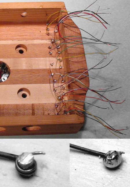
Now solder wire to the pegs. To enough pieces of the thinner multicolor node
wire, strip 1" off one end and 1/8" off the other. To solder to a
peg: with needlenose pliers, wrap the long end of the node wire a few times
around the peg. now heat the joint up real good with the soldering iron, then
push some solder in. If it doesn't push in smoothly, you must wait longer to
heat it up. The big copper pins take a long time to do right. Test your soldering
by tugging not hard enough to break the wire.
Mounting
Let's screw the circuit board
to the case. First, clean the holes for the shafts of the nobs. Use a file,
and test fit the board to make sure they all can rotate freely. On the inside
of the case, there are little pilot holes for the screws. On each one, glue
a spacer down. Since it only needs to be a temporary glue, I used white glue.
This makes sure they stay in place while you fit the circuit board on top of
them. Screw the circuit board down. Use the longer #4-5/8" sheet metal
screws.
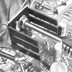
Screw the heatsink onto the regulator like shown, using enclosed machine screw,
nut, and washer.
Jacks
This is a DC jack. It will connect to the wallwart, which converts AC line voltage
to DC. It fits into the 1/2" hole on the power side of the case. Rub epoxy
around the inside of the hole with a toothpick, and push the jack in.
This is a 9 volt battery connector, in case you play in a location without AC
line power. In the shallow dish on the power side of the case, make a pool of
epoxy, then feed the wires through the little hole there and push the connector
down into the pool. Tape it down so it can set up in place. Now the connector
is on the outside of the box and you will be able to change the battery any
time you want.
Now let's wire the power, using the thicker monocolor wire. the black wire from
the battery goes over to the middle pin on the DC jack, and the red one connects
to the the "B"-PAD on the power insignium of the circuit board. The
"P"-PAD connects to the big pin on the DC jack, and the outermost
pin of the DC jack connects to a ground node (thos with circles and round decorations)
in the power insignium.
Use wire long enough to reach. Strip both ends, solder well, and trim. Make
sure no unplanned pins are connected, because this is high current power! You
notised: the black wire coming from the battery is a ground, but why is not
connected directly to a ground node? The DC connector will switch it off whenever
a wallwart is plugged in, just to make sure the battery is not being used then.
Now that this is wired up, let's test to see if your kit works. Briefly plug
the wallwart into the wall and connect it to the DC power jack. If no work:
fiddle with the knobs, then unplug the machine and inspect the circuit board
for solder bridges, unconnected parts, or reversed diodes. This is where you
must stop and fix things. If nothing still works, email me. We will work it
out.
Wire the jacks like shown, then install with plastic nuts. To the left, the inward
toothed symbol is inputs. To the right, the outward toothed symbol is outputs.
Sensore and Sandrode wiring
On the inside of the case, wire to the big copper sensor pins like this. These
are the filter modulation inputs. One affects its frequency verso, the other
affects it inverso. The rest of the brassos can go randomly to any of the number
squares, which are the divider outputs.
Your kit should be done now! Test it out then screw the bottom back on.
Wallwart Wiring
Wallwarts can be found at any thrift store, closet, on the street, they are
everywhere, since they power most low voltage consumer electronics. We need
one that is DC (Direct Current), not AC (Alternating Current). We need it to
produce between 9-18 Volts, with a minimum of 300ma (300 Milliamperes) of current.
Your kit is wired to handle overvoltages, and it regulates whatever input voltage
internally down to a steady 9 volts. The plug on the end of the wallwart you
found may just fit the kit. Try it- the duber is protected internally against
reverse power. If the end does not fit, it's pretty easy to rewire it. Unscrew
the plug provided with the kit, and slip the cap onto the wire before you solder
it! Now strip both ends of the two wires. The wire with the stripe is most often
positive, which connects to the smaller tab. The solid wire is ground, which
connects to the large tab. In rare incidences, this is reversed, so if your
kit doesn't work, try flipping the wires until it works.